
High-power light emitting diodes (high-power LEDs) can be 350 milliwatts or more strong in a single LED. Most of the energy in an LED is converted into heat rather than light (about 70% heat and 30% light). If this heat cannot be dissipated, the LEDs glow at very high temperatures. This not only lowers the efficiency, but also shortens the lifespan of the LED. Therefore, the thermal management of high-power LEDs is an essential area of research and development. It is necessary to limit the Junction Temperature of a value that ensures the desired LED life.
Heat transfer
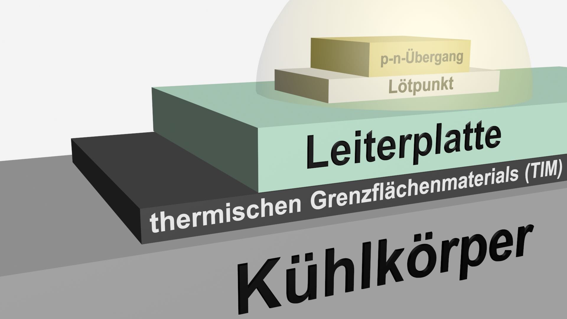
To maintain a low lock layer temperature that maintains the high power of an LED, any possibility of heat removal from LEDs should be considered. Heat conduction (reduction), heat removal by air (convection) and radiation are the three possibilities for heat transfer. Typically, LEDs are encapsulated in a transparent resin, which is a bad heat conductor. Almost all of the heat generated is passed through the back of the chip. Heat is generated by the p-n transition by electrical energy that has not been converted into useful light. It reaches the soldering point via a long distance from the connection point, the soldering point to the circuit board and the circuit board to the heat sink and is then directed to the atmosphere of the external environment.
The barrier layer temperature is lower if the thermal impedance is smaller or the ambient temperature is lower. To maximize the usable ambient temperature range for a given loss performance, the total heat resistance from the connection point to the environment must be minimized.
Heat resistance values vary widely depending on the material and adjacent components. For example, RJC ( thermal resistance barrier layer to housing) ranges from 2.6 ° C/W to 18 ° C/W depending on the LED manufacturer. The thermal resistance of the thermal conduction material (also TIM: Thermal Interface material) also varies depending on the type of material selected. Guying TIMs are epoxy, thermal paste, adhesive and lot. High-power LEDs are often mounted on metal core circuit boards (MCPCBs) attached to a radiator. Heat passed through the metallic module plate and the heat-conducting radiator is then dissipated by convection and radiation. In addition to the design and design of the cooling body, the surface evenness and quality of each component, the pressure, the contact surface, the type of thermal conduction material and its thickness are. These are parameters for heat resistance or cooling of the LED through heat removal.
Passive cooling
Factors for passive cooling for efficient heat management of high-power LEDs are:
Thermal conductor
Thermal conductor is normally used to connect LED to the board and the board to the radiator. The use of a thermal conductor can further optimize the heat output.
Heat sink
Heat sinks contribute significantly to the removal of heat. It functions as a conductor that directs heat from the LED source to the outer medium. Heat sinks can deduce energy in three ways: Heat conduction (reduction: Heat transfer within or from one solid to another), convection (heat transfer from one solid to a moving fluid, for most LED applications is The fluid the ambient air) or radiation (heat transfer of two bodies of different surface temperatures through heat radiation).
- Material:
The thermal conductivity of the material that makes up the radiator directly affects the loss performance of the thermal conduction. Normally, aluminium is used because of the very good value for money. In the case of flat coolers, copper is often used, despite the high purchase price. New materials include thermoplastics, which are used when heat dissipation requirements are lower than normal (e.g. often in home requirements) or complex shapes in the spray casting process make sense. Graphite solutions often have a more effective heat transfer (not thermal conduction) than copper at a lower weight than aluminium. Graphite is considered an exotic cooling solution and is more expensive to produce. Heat pipes can also be added to aluminum or copper coolers to reduce dispersal resistance.
- Form:
The heat transfer takes place on the surface of the cooler. Therefore, heat sinks should be designed to have a large surface area. This can be achieved by using a large number of fine ribs or by enlarging the radiator itself.
Although a larger surface area leads to better cooling performance, there must be enough space between the ribs to create a considerable temperature difference between the cooling rib and the ambient air. If the ribs are too close to each other, the air in between can have almost the same temperature as the ribs, so no heat transfer takes place. As a result, more cooling ribs do not necessarily lead to more cooling power.
- Texture:
Heat radiation of coolers is a function of surface texture, especially at higher temperatures. A painted surface has a greater emission level than a bright, unvarnished surface. The effect is most notable for shallow coolers, where about a third of heat is dissipated by radiation. In addition, an optimal flat contact surface allows the use of a thinner thermal conduction paste, which reduces the heat resistance between the heat sink and the LED source. On the other hand, anodising or etching also reduces thermal resistance.
- Installation method:
Cooling body fasteners with screws or feathers are often better than conventional clips, thermal conductor or tape. For heat transfer between LED sources over 15 watts and LED coolers, it is recommended to use a high-heat conducting interface material (TIM) that has a heat resistance above the interface of less than 0.2 K/W. Currently, the most common method used is a phase change material that is applied at room temperature in the form of a solid pillow, but then converts into a thick gelatinous liquid as soon as it rises above 45 ºC.
Heat pipes and steam chambers
Heat pipes and steam chambers have passive effects and their thermal conductivity capabilities are very effective from 10,000 to 100,000 W/mK. They offer the following advantages in LED heat management:
- Transports heat to another radiator with minimal temperature drop
- Isothermizes heat control through natural convection, increasing efficiency and reducing its size. It is a case known in which the addition of five heat pipes reduced the heat conflux mass by 34% from 4.4 kg to 2.9 kg.
- The high heat flow directly under an LED efficiently into a lower heat flow, which can be dissipated more easily.
PCB (tight: Pressed circuit board)
- MCPCB:
MCPPCB (Metal Core PCB) are boards that contain a base metal material for heat distribution as an integral part of the circuit board. The metal core usually consists of an aluminium alloy. MCPCB has the advantage of a dielectric polymer layer with a high thermal conductivity.
- Separation:
Separating the LED driver circuit from the LED board prevents the heat generated by the driver from increasing the LED lock layer temperature.
Platinum coating
- Additive process:
On the PCBs, conductive substances are applied to the carrier material during the production process for the creation of conductive structural surface. The conductor is only applied to the predetermined conductor’s track image. In contrast, this is etched away in the subtractive process. Basically, there is a direct connection to the aluminium radiator; For example, no additional material for the thermal connection is required for the circuit. This reduces the heat-conducting layers and heat surface. Processing steps, types of materials and material quantities are reduced.
Aluminium ladder plates (also known as IMS circuit boards for Insulated Metal Substrates)-It increases thermal connection and provides a high dielectric penetration voltage. Materials tolerate heat up to 600 ° C. The circuits are directly attached to aluminium substrates, so no thermal conduction materials are required. The improved thermal connection can reduce the lock layer temperature of the LED by up to 10 ° C. This allows the developer to reduce the number of LEDs required on a board by increasing performance for each LED. It can also reduce the size of the substrate to meet dimensional limitations. It has been proven that a reduction in the transition temperature greatly increases the lifespan of the LED.
Form factor
- Flip chip:
The LED chip is mounted with the front down on the mount, which is usually made of silicon or ceramic and is used as a heat distributor and carrier substrate. The flip-chip connection can be eutectic, leaded, unleaded or gold stub. The primary light source comes from the back of the LED chip. A reflective layer is usually built in between the light emitter and the soldering sites to reflect the light emitted downwards. Several companies use flip-chip cases for their high-power LED, reducing LED thermal durability by about 60%. At the same time, thermal reliability will be maintained.