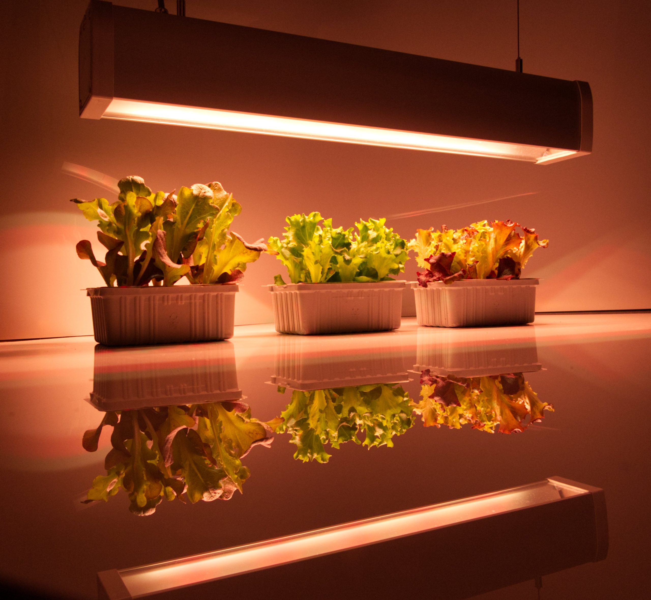
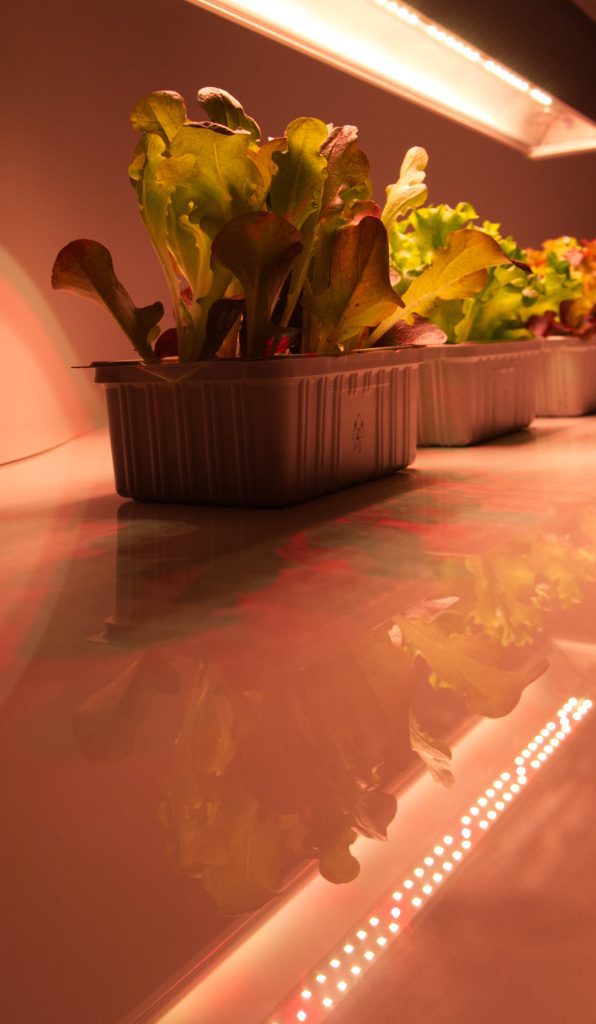
Die Zucht von Pflanzen im Innenraum erfreut sich zunehmender Beliebtheit, sei es aus Hobby, aus wirtschaftlichen Gründen oder zur Selbstversorgung. Mit den Fortschritten in der Lichttechnologie, insbesondere mit der Entwicklung der LED-Beleuchtung, hat sich die Indoor-Pflanzenzucht erheblich verbessert. Hier sind die wichtigsten Vorteile der LED-Beleuchtung in diesem Bereich:
Energieeffizienz: LED-Leuchten verbrauchen deutlich weniger Energie als herkömmliche Beleuchtungssysteme wie Leuchtstofflampen oder HID-Lampen. Das bedeutet geringere Stromrechnungen trotz gleichbleibender oder sogar verbesserter Lichtausbeute.
Langlebigkeit: LEDs haben eine deutlich längere Lebensdauer als andere Lichtquellen. Einige LEDs können bis zu 50.000 Stunden oder länger halten, wodurch die Notwendigkeit häufiger Wechsel reduziert und damit auch die Wartungskosten gesenkt werden.
Spektrale Anpassungsfähigkeit: LEDs können in einem breiten Spektrum von Farben produziert werden, was bedeutet, dass sie speziell für die spezifischen Bedürfnisse verschiedener Pflanzenarten angepasst werden können. Dies ermöglicht es den Züchtern, das Lichtspektrum genau auf die Bedürfnisse ihrer Pflanzen abzustimmen, was den Wachstumsprozess optimiert.
Weniger Wärme: Während andere Lichtquellen erhebliche Mengen an Wärme abgeben können, die das Raumklima beeinflussen und sogar Pflanzen schädigen können, erzeugen LEDs deutlich weniger Wärme. Dies minimiert das Risiko von Wärmeschäden und erleichtert die Temperaturkontrolle im Anbauraum.
Kompakte Bauweise: Die kompakte Größe und das leichte Design von LED-Leuchten erleichtern ihre Installation und Anpassung, insbesondere in begrenzten Räumen oder spezialisierten Zuchtumgebungen.
Kostenersparnis langfristig: Obwohl die anfänglichen Kosten für LED-Beleuchtungssysteme höher sein können als für traditionelle Systeme, werden diese Kosten oft durch die Energieeinsparungen, die längere Lebensdauer und die verringerten Wartungskosten ausgeglichen.
Sicherheit: LEDs enthalten keine gefährlichen Chemikalien wie Quecksilber, das in vielen anderen Leuchtmitteln zu finden ist. Darüber hinaus reduziert ihr kühlerer Betrieb das Risiko von Bränden.
Verbesserter Pflanzenwuchs: Studien haben gezeigt, dass Pflanzen unter LED-Licht oft schneller wachsen und höhere Erträge erzeugen können, insbesondere wenn das Lichtspektrum genau auf ihre Bedürfnisse abgestimmt ist.
Zusammenfassend lässt sich sagen, dass die LED-Beleuchtung eine revolutionäre Technologie für die Indoor-Pflanzenzucht darstellt. Durch ihre zahlreichen Vorteile bieten sie Züchtern die Möglichkeit, effizienter, kostengünstiger und umweltfreundlicher zu arbeiten.
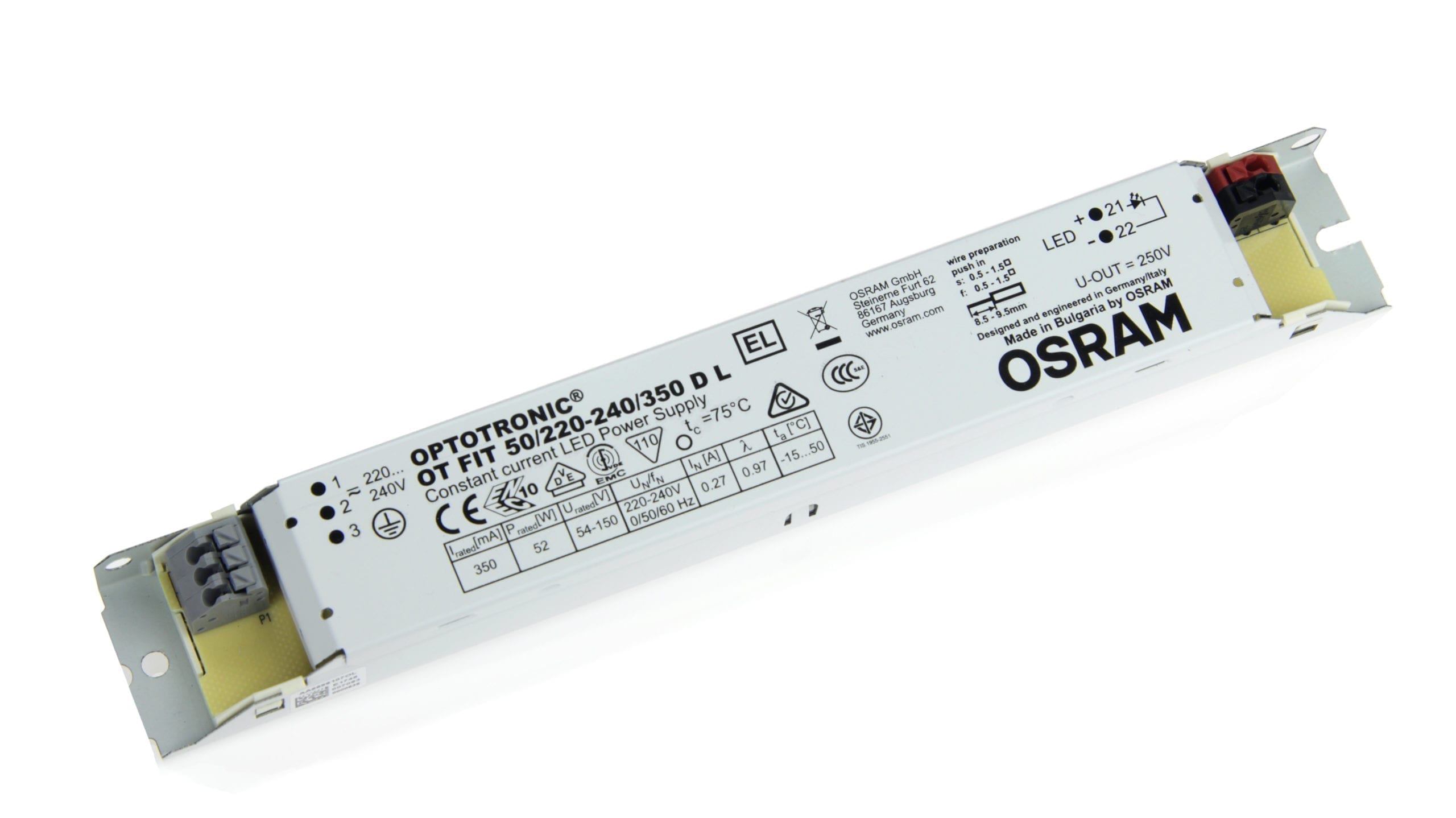
Guide to choosing the right LED driver. It contains basic points that should be considered when selecting an LED driver in the application. Here is some background information on basic points to help the user make the right decision and choice.
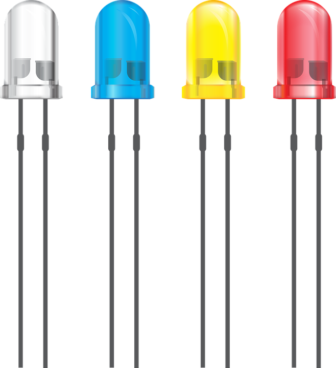
Led DIP chip (dual in-line package)
Dual In-Line Package (Dual In-Line Package) LEDs are the traditional original LED bulbs.
Although DIP chips are still in use today, they have much lower efficiency than the newer LED chips used for modern applications. They are more commonly used in electronics.
An LED DIP chip typically produces about 4 lumens per LED, much less than the newer chips and is used in simple plug and surface assembly.
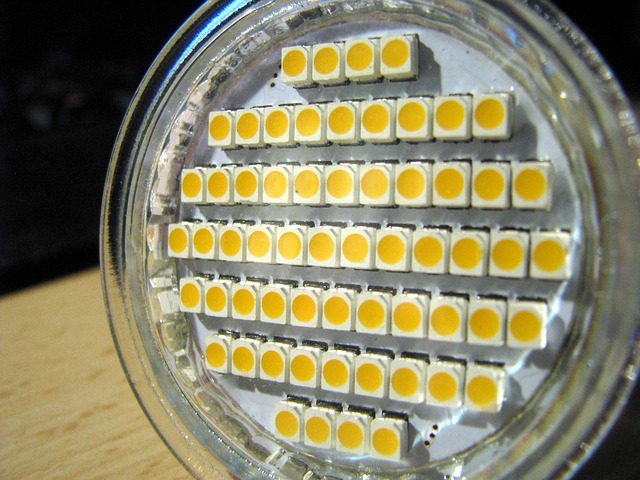
Led SMD chip
SMD stands for “Surface Mounted Diode” and are much smaller and more efficient LEDs than the original DIP chips. They have become indispensable due to a wide range of possible applications and are typically mounted and soldered on a circuit board (module). SMD chips have become very important for the development of the LED industry, as 3 diodes can be accommodated on the same chip.
In addition to the significantly more efficient brightness, they can also change the color. Some of the LED chips can now be produced so small that they are installed in high-end electronics such as mobile phone control lights.
They are also used as standalone chips predominantly in LED strips or LED spotlights and in the industry on LED modules.
SMD chips can generate between 50 and 100 lumens per watt. This is much more efficient to the DIP chip.
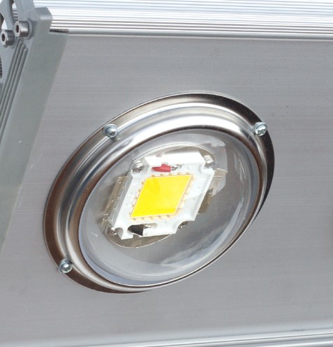
Led COB Chip
COB (Chip on Board) LED is a high performance leather chip (high power LED). A COB chip has several internally installed diodes, typically more than 9. Simplified COB can be described in such a way that several SMD chips are installed on a board and thus generate significantly more light due to the special design.
COB chips are used in many different devices. In small devices such as cameras and smartphones, this is due to the high lumence count, which requires little energy.
Often LED COB chips are used in floodlights and high-performance LED headlights and spotlights. Since different designs are possible with COB chips, a lot of lumen can be produced per watt, which are usually well over 100 lm/W.
Combined applications of SMD or COB chips are used in LED arrays (single or multiple LEDs pre-mounted on a circuit board), LED strips (for linear LED use), and LED modules with directly installed mini drivers (LED light engines).
Constant current vs. constant voltage
Drivers use either constant current (CC) or constant voltage (CV) or both. This is one of the first points that needs to be taken into account in the decision-making process. This depends on the LED or LED module to be controlled. The information can be found on the LED data sheet.
What is Constantstrom?
Constantstrom (also CC for constant) LED drivers maintain a constant electric current (A) by having a variable voltage (V). CC drivers are often the preferred choice for LED applications. CC LED drivers can be used on individual lights or LEDs switched in series. The downside is that if the switching path is interrupted at one point, the remaining LEDs will no longer work. However, constant current drivers generally provide better control and are more efficient than drivers with constant voltage.
What is constant tension?
Light drivers with constant voltage (CV) are power supplies. They have a fixed voltage that they deliver to the electronic circuit. You could use CV LED drivers to run multiple LEDs in parallel, for example with LED strips. CV power supplies can be used on LED strips that have power limit resistance, which is usually the case. The voltage output must meet the voltage requirements of the entire LED chain.
CV drivers can also be used on LED light engines that have a driver IC installed.
What is Constantstrom and what is constant tension?
Some LED drivers can offer both possibilities (CV and CC). By default, they work as CV, but when the output current exceeds the face current limit, they switch to a CC mode. This feature is suitable for applications that require a flexible LED driver.
When should you use CV-or CC drivers (exceptions possible)?
Constantstrom (CC)
Constant voltage (CV)
Led Downlights/built-in lights
LEDs parallel
Office lighting
Led stripes
Residential LED lighting
Led Light Engines
Mood light
Moving signs/characters
Retail/commercial lighting
Stage lighting
Entertainment lighting
Architectural lighting
Led signs
Streetlights
Streetlights
Indirect lighting (drywall)
High Bay
Outdoor lighting
Architectural lighting
Led strips (high-power LED)
Workplace lighting
Factors to consider:
Outsource current (mA)
When using a constant current LED driver, it must be adapted to the requirements of the selected LEDs. Power values of drivers and LEDs must match. The data sheets of the LEDs indicate which power values are needed. The value is given in amps (A) or milliampers (mA). 1 A are 1000 mA.
There are also variable and selectable constant power drivers. There are Constant power drivers either in the range of 0 to 500 mA or in fixed values such as 350 mA, 500 mA, 700 mA, 1050 mA and more. The LEDs must match these chosen values.
LEDs should be operated at the lowest possible current in order to extend the lifespan and to increase lm/W efficiency. When using more power, LEDs usually wear out faster. It is therefore advisable to think about using more LED modules together and thus reduce the respective current strength. As a rule, the LED data sheets show the different efficiency in lm/W with different electricity.
Starting power (W)
This value is given in watts (W). LED drivers should operate at least the same value of the LEDs.
The driver should have a higher output output of at least. 10% to have power reserves for running the LEDs. If the driver power is the same as the LED power, the driver would be at full occupancy all the time. With full power utilization, this would shorten the driver’s lifespan. Lifespan is an additional important decision-making factor when using and operating drivers correctly.
The performance requirement of LEDs is basically given as an average value. This means that LEDs require a +/-rabance dance in performance. Therefore, it is important to ensure that the driver can meet a possible increased performance requirement.
Output voltage (V)
This value is given in Volt (V). In the case of constant voltage drivers, the voltage must be the same as the one provided by the LED. With multiple LEDs, voltage values are added to a total value. In the case of constant current, the voltage must be higher than that of the LEDs.
Life expectancy
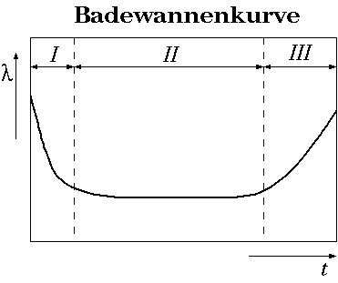
The life expectancy of drivers is given in hours. This is related to the average operating time (MTBF = mean time between failures). Based on this value, drivers should also be compared when making a purchase decision. The right operation can extend the lifespan. This reduces maintenance time/costs.
It should be mentioned, however, that this is a statistical value. While this is an indicator of comparing different products. However, it should be known that the value is determined as follows. Basically, the failure warning symptoms of the individual components are summed up. On the other hand, the information should be broken down into three areas in real terms: 1. “Early outages,” 2. “usable lifespan” and 3. “End-of-Time section.” The MTBF usually specifies only the middle section. This eliminates “teething problems” and “ageing effect.” As a result, the MTBF can usually be specified with several million hours.
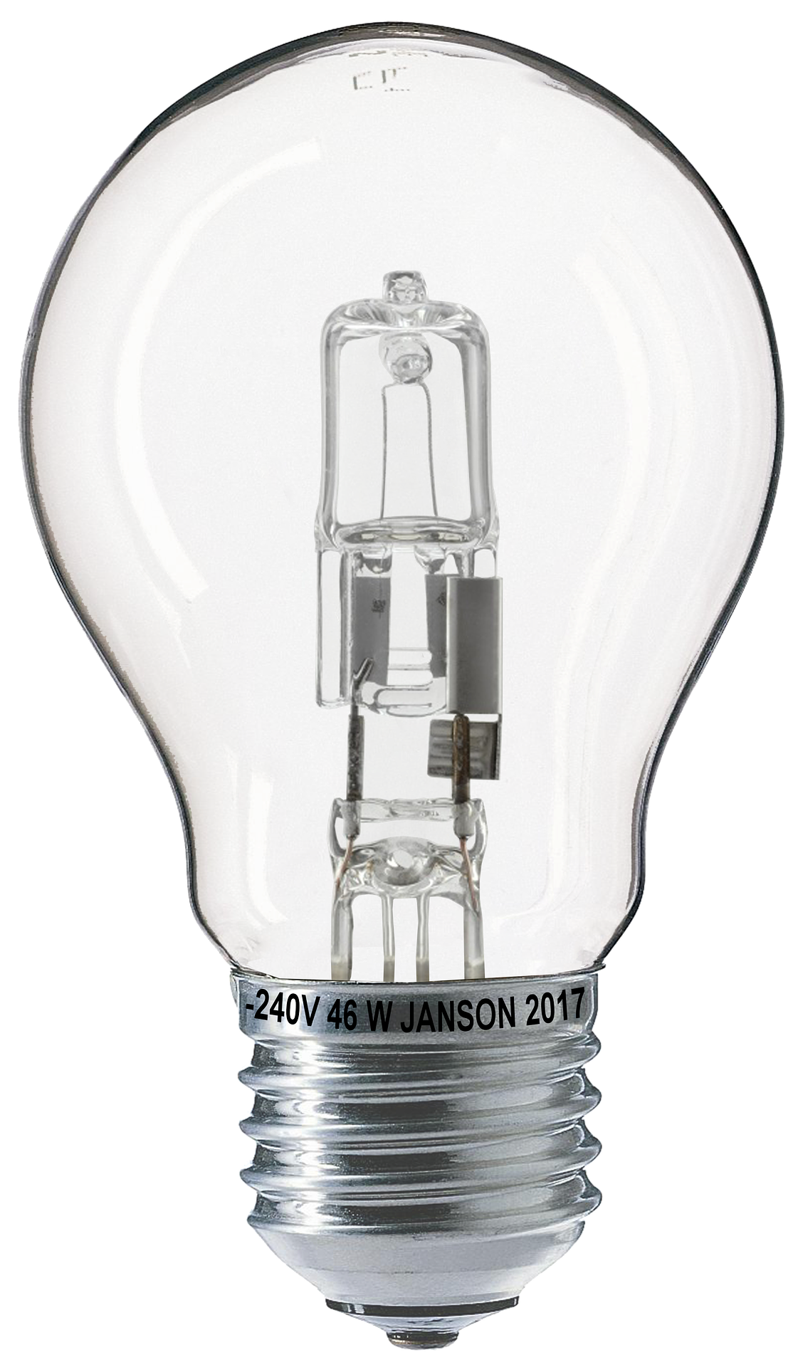
As of 01.09.2018, the sale of low-voltage halogen lamps and HV lamps is prohibited. We provide you with the most important background information.
The European Union (EU) has determined that energy consumption should be gradually reduced, thereby protecting the environment. And the ban on the use of mercury in luminaires is designed to provide greater safety.
Consequently, the LED is becoming a mandatory must-have across Europe. Nevertheless, the costs are often amortized after about 3 years and the lifespan is usually far from finished.
But now to the background. The EU introduced the so-called light bulb ban in 2009. Many remember the subsequent almost panicked hamster purchases of incandescent bulbs. As a result, the development and sale of LED and fluorescent tubes has been massively advanced. The ban was phased in. In this way, the EU is actively trying to reduce energy consumption in the private and commercial sectors. As with the “incandescent bulb ban” in 2009, residual stocks may continue to be sold and used. Since 2016, the sales ban has been extended to many fluorescent tubes. These are to be banned outright under the “Ecodesign Directive” from 2020. The reason here is the extremely toxic mercury. As the demand for the efficiency of the light bulb increases at the same time, from 2020 only T5 fluorescent tubes, most efficient halogen metal vapour lamps and low-pressure sodium vapour lamps and, of course, LED (1) will be available to us.
As of 01.09.2018, the sale of all halogen and incandescent bulbs is prohibited, the efficiency of which is worse than Class B. Exceptions are clear halogen lights with R7s or G9 plinths. In addition, the regulation also lists, among other things, the following exceptions:
The requirements of this regulation do not apply to the following household and special lamps
Lamps with bundled light
Lamps with a stream of light below 60 lumens or over 12,000 lumens
Fluorescent lamps without a built-in ballasts
High-pressure discharge lamps
It should be noted that fluorescent tubes must be collected and disposed of correctly when retrofitting to LED. Because of the mercury content, fluorescent tubes are not allowed into household waste or glass containers. Delivery of old fluorescent tubes is possible in the following places:
Retailers must take this product back, but of course the previous purchase must be substantiated
Supermarkets and drugstores often offer collection points for light bulbs
Local recyclable yard
Should a fluorescent tube break, caution should be maintained in any case. If a fluorescent tube is broken, we recommend the immediate ventilation of the room, absolutely avoid skin contact, wear gloves at the removal, instead of using the hand sweep a piece of cardboard to bring together, pick up other splinters with damp cloth and absorb everything Leave to be professionally recycled in a sealable vessel at the recyclable yard. The gloves used, heavily soiled clothing, used cloths, etc. should also be fed to the garbage.
Definition:
EU Directive: Individual member states can decide for themselves how to implement EU directives. So there is some room for manoeuvre in the implementation.
EU regulation: They are directly effective and binding on each Member State and must be implemented.
High-power light emitting diodes (high-power LEDs) can be 350 milliwatts or more strong in a single LED. Most of the energy in an LED is converted into heat rather than light (about 70% heat and 30% light). If this heat cannot be dissipated, the LEDs glow at very high temperatures. This not only lowers the efficiency, but also shortens the lifespan of the LED. Therefore, the thermal management of high-power LEDs is an essential area of research and development. It is necessary to limit the Junction Temperature of a value that ensures the desired LED life.
Heat transfer
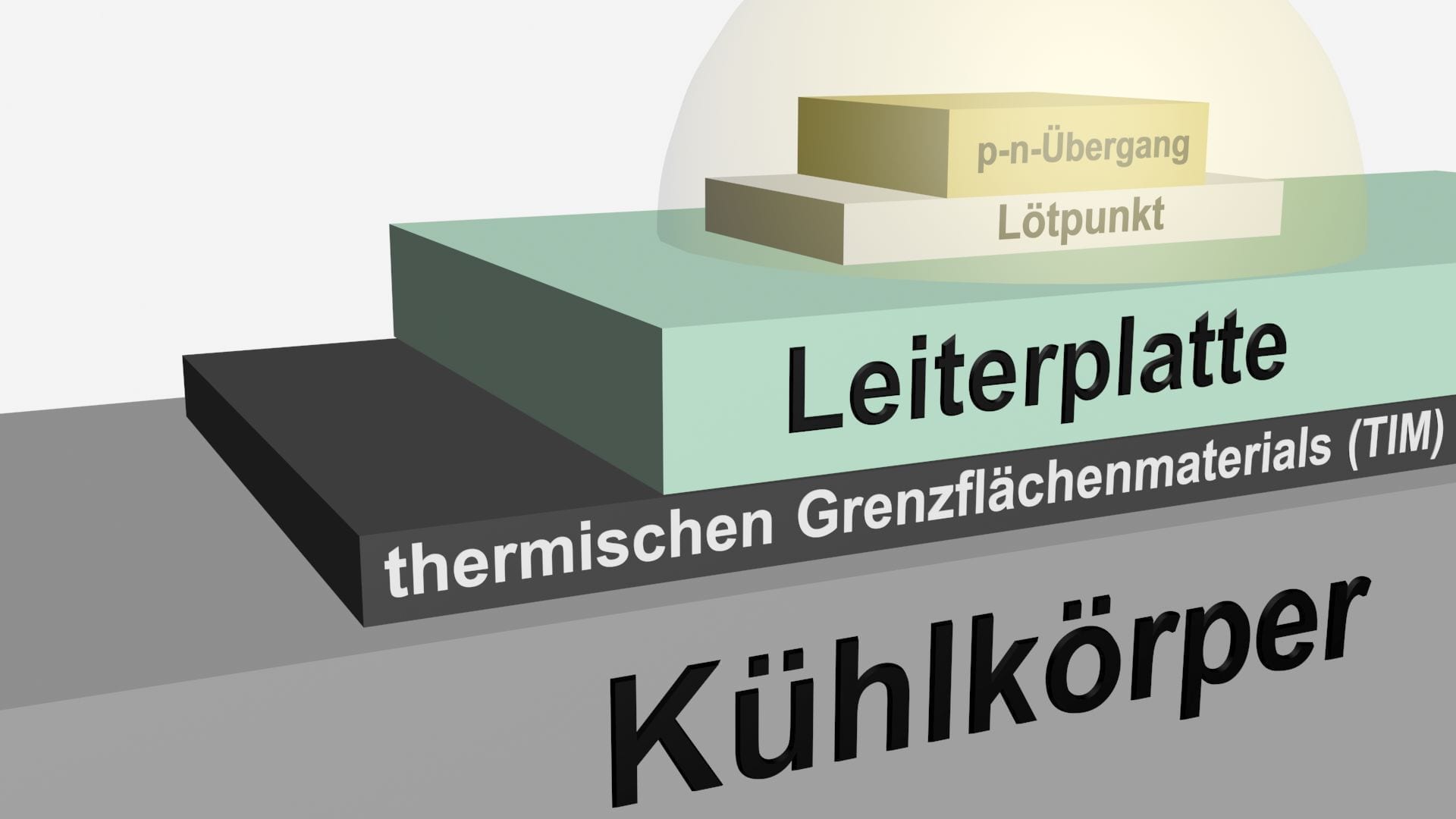
To maintain a low lock layer temperature that maintains the high power of an LED, any possibility of heat removal from LEDs should be considered. Heat conduction (reduction), heat removal by air (convection) and radiation are the three possibilities for heat transfer. Typically, LEDs are encapsulated in a transparent resin, which is a bad heat conductor. Almost all of the heat generated is passed through the back of the chip. Heat is generated by the p-n transition by electrical energy that has not been converted into useful light. It reaches the soldering point via a long distance from the connection point, the soldering point to the circuit board and the circuit board to the heat sink and is then directed to the atmosphere of the external environment.
The barrier layer temperature is lower if the thermal impedance is smaller or the ambient temperature is lower. To maximize the usable ambient temperature range for a given loss performance, the total heat resistance from the connection point to the environment must be minimized.
Heat resistance values vary widely depending on the material and adjacent components. For example, RJC ( thermal resistance barrier layer to housing) ranges from 2.6 ° C/W to 18 ° C/W depending on the LED manufacturer. The thermal resistance of the thermal conduction material (also TIM: Thermal Interface material) also varies depending on the type of material selected. Guying TIMs are epoxy, thermal paste, adhesive and lot. High-power LEDs are often mounted on metal core circuit boards (MCPCBs) attached to a radiator. Heat passed through the metallic module plate and the heat-conducting radiator is then dissipated by convection and radiation. In addition to the design and design of the cooling body, the surface evenness and quality of each component, the pressure, the contact surface, the type of thermal conduction material and its thickness are. These are parameters for heat resistance or cooling of the LED through heat removal.
Passive cooling
Factors for passive cooling for efficient heat management of high-power LEDs are:
Thermal conductor
Thermal conductor is normally used to connect LED to the board and the board to the radiator. The use of a thermal conductor can further optimize the heat output.
Heat sink
Heat sinks contribute significantly to the removal of heat. It functions as a conductor that directs heat from the LED source to the outer medium. Heat sinks can deduce energy in three ways: Heat conduction (reduction: Heat transfer within or from one solid to another), convection (heat transfer from one solid to a moving fluid, for most LED applications is The fluid the ambient air) or radiation (heat transfer of two bodies of different surface temperatures through heat radiation).
Material:
The thermal conductivity of the material that makes up the radiator directly affects the loss performance of the thermal conduction. Normally, aluminium is used because of the very good value for money. In the case of flat coolers, copper is often used, despite the high purchase price. New materials include thermoplastics, which are used when heat dissipation requirements are lower than normal (e.g. often in home requirements) or complex shapes in the spray casting process make sense. Graphite solutions often have a more effective heat transfer (not thermal conduction) than copper at a lower weight than aluminium. Graphite is considered an exotic cooling solution and is more expensive to produce. Heat pipes can also be added to aluminum or copper coolers to reduce dispersal resistance.
Form:
The heat transfer takes place on the surface of the cooler. Therefore, heat sinks should be designed to have a large surface area. This can be achieved by using a large number of fine ribs or by enlarging the radiator itself. Although a larger surface area leads to better cooling performance, there must be enough space between the ribs to create a considerable temperature difference between the cooling rib and the ambient air. If the ribs are too close to each other, the air in between can have almost the same temperature as the ribs, so no heat transfer takes place. As a result, more cooling ribs do not necessarily lead to more cooling power.
Texture:
Heat radiation of coolers is a function of surface texture, especially at higher temperatures. A painted surface has a greater emission level than a bright, unvarnished surface. The effect is most notable for shallow coolers, where about a third of heat is dissipated by radiation. In addition, an optimal flat contact surface allows the use of a thinner thermal conduction paste, which reduces the heat resistance between the heat sink and the LED source. On the other hand, anodising or etching also reduces thermal resistance.
Installation method:
Cooling body fasteners with screws or feathers are often better than conventional clips, thermal conductor or tape. For heat transfer between LED sources over 15 watts and LED coolers, it is recommended to use a high-heat conducting interface material (TIM) that has a heat resistance above the interface of less than 0.2 K/W. Currently, the most common method used is a phase change material that is applied at room temperature in the form of a solid pillow, but then converts into a thick gelatinous liquid as soon as it rises above 45 ºC.
Heat pipes and steam chambers
Heat pipes and steam chambers have passive effects and their thermal conductivity capabilities are very effective from 10,000 to 100,000 W/mK. They offer the following advantages in LED heat management:
Transports heat to another radiator with minimal temperature drop
Isothermizes heat control through natural convection, increasing efficiency and reducing its size. It is a case known in which the addition of five heat pipes reduced the heat conflux mass by 34% from 4.4 kg to 2.9 kg.
The high heat flow directly under an LED efficiently into a lower heat flow, which can be dissipated more easily.
PCB (tight: Pressed circuit board)
MCPCB:
MCPPCB (Metal Core PCB) are boards that contain a base metal material for heat distribution as an integral part of the circuit board. The metal core usually consists of an aluminium alloy. MCPCB has the advantage of a dielectric polymer layer with a high thermal conductivity.
Separation:
Separating the LED driver circuit from the LED board prevents the heat generated by the driver from increasing the LED lock layer temperature.
Platinum coating
Additive process:
On the PCBs, conductive substances are applied to the carrier material during the production process for the creation of conductive structural surface. The conductor is only applied to the predetermined conductor’s track image. In contrast, this is etched away in the subtractive process. Basically, there is a direct connection to the aluminium radiator; For example, no additional material for the thermal connection is required for the circuit. This reduces the heat-conducting layers and heat surface. Processing steps, types of materials and material quantities are reduced.
Aluminium ladder plates (also known as IMS circuit boards for Insulated Metal Substrates)-It increases thermal connection and provides a high dielectric penetration voltage. Materials tolerate heat up to 600 ° C. The circuits are directly attached to aluminium substrates, so no thermal conduction materials are required. The improved thermal connection can reduce the lock layer temperature of the LED by up to 10 ° C. This allows the developer to reduce the number of LEDs required on a board by increasing performance for each LED. It can also reduce the size of the substrate to meet dimensional limitations. It has been proven that a reduction in the transition temperature greatly increases the lifespan of the LED.
Form factor
Flip chip:
The LED chip is mounted with the front down on the mount, which is usually made of silicon or ceramic and is used as a heat distributor and carrier substrate. The flip-chip connection can be eutectic, leaded, unleaded or gold stub. The primary light source comes from the back of the LED chip. A reflective layer is usually built in between the light emitter and the soldering sites to reflect the light emitted downwards. Several companies use flip-chip cases for their high-power LED, reducing LED thermal durability by about 60%. At the same time, thermal reliability will be maintained.